A Simple Medium Vacuum System


Integrating a pump and gauge with a simple manifold to make flexible foundation for experiments in the medium vacuum range
This original version of this article appeared in Volume 4, Number 4 of the Bell Jar with additional material added.
Introduction
The system that is described here was designed to be inexpensive, portable and flexible. It has been used at recent AVS education sessions including the Educators’ Workshop and the Education Outreach program.
The typical classroom-type vacuum system consists of a metal baseplate with rubber gasket that is mounted on a small single-stage vacuum pump. A glass or plastic bell jar, placed on the baseplate, is used as the chamber. Such a system is usable for a number of demonstrations in physics. However, the pumps are generally unsuitable for pressures below a Torr or so, the gauging (typically a 0-30 inch Hg Bourdon gauge) is crude, the bell jar configuration limits flexibility, and controlling the pressure at a given level of vacuum is not easily possible.
To address the above, I came up with the little table-top system shown in Figure 1. It uses the 2-stage refrigeration service vacuum pump and thermocouple gauge that have been described elsewhere. The manifold was assembled on top of a small laminated hardwood kitchen breadboard, equipped with a set of rubber feet.
No dedicated chamber is shown with this system. Instead, there is a standard O-ring flange at the top of the manifold. This can be used to couple the manifold to a variety of chambers. We will start by describing this flange.
The KF Flange System
Flanges are the standard component to use when attaching a tube to another similar tube where it is desired to be able to disconnect one from the other. A wide variety of flanges are available and many are expensive. A very versatile commercial flange for amateur use is the KF (from the German Klein Flansch or “small flange,” also known as QF or “Quick Flange”) system. KF assemblies are relatively inexpensive and, depending upon the materials selected (brass or stainless steel), are compatible with soldering or brazing to standard inch dimensioned copper tubing (e.g. common water tube) or welding to common sizes of stainless steel tubes.
The KF flange system is depicted in Figure 1. To make a complete connection there are five components: two similar flanges (each of which may accommodate a slightly different diameter tube), a metal center-ring that supports the O-ring and keeps the flanges in alignment, the O-ring itself, and a clamp (not shown) that, by means of a thumb screw, compresses and holds the entire assembly together.
Five sizes of KF flange are available that can accommodate tubes from 1/2" through 2-1/8" diameter. Center-rings are available that have screens to prevent loose debris from passing through the flange. Also, adaptive center-rings are available that permit the coupling of some adjacent sizes of KF flange. I've found the KF25 brass flange, sized for 1 inch copper water tube (1-1/8" od), and the KF40, sized for 1-1/2" water tube (1-5/8" od) to be the most versatile in small vacuum apparatus. A complete brass QF25 assembly with Buna-N O-ring will cost about thirty dollars. As each additional KF25 flange is only about $9, the KF system is an inexpensive route to take when multiple flanged devices are to be attached, one at a time, to a system. A complete KF40 assembly is about forty dollars. Viton O-rings may be substituted at additional cost. These have better high temperature and outgassing properties.
Manifold Description
With the exception of the KF flange, all of the plumbing is right from the hardware store. All solder joints are made with tin-2% silver soft solder and the threaded connections that are not intended to be taken apart are sealed with household epoxy. A 1/4-20 brass bolt is soldered to the tubing cap at the lower end of the system. This bolt is used to mount the manifold to the wooden base. A 5/8 inch hose barb serves as the connection to the mechanical pump via a short length of PVC tubing (remember, you don't want to compromise the pumping speed too much).
There are two side-arms that are fabricated from 1/8 inch threaded brass fittings. The first connects to a pair of gauges: a Bourdon vacuum gauge of the type used for automotive engine testing, and a thermocouple gauge tube. The second arm is connected to a simple needle valve that is used as an air leak. This serves as a pressure control. I got this valve from American Science and Surplus for about $5.00. It is all stainless with a Teflon packing. Also connected to this arm is the system vent, a short length of rubber tubing with a pinchcock.
Having the two gauges is, of course, necessary if experiments are to be conducted across the entire rough and medium vacuum range. Additionally, if the system is to be used for classroom demonstrations, the dual gauges help to illustrate that there's still quite a bit to vacuum below where the Bourdon gauge bottoms out.
Having some sort of pressure control on a system such as this is important for showing the different effects that occur at various pressures. With the metering valve and with some adjusting of the pump’s isolation valve, it is a simple matter to adjust and maintain the pressure with coarse precision at any value between 30 milliTorr and atmosphere.
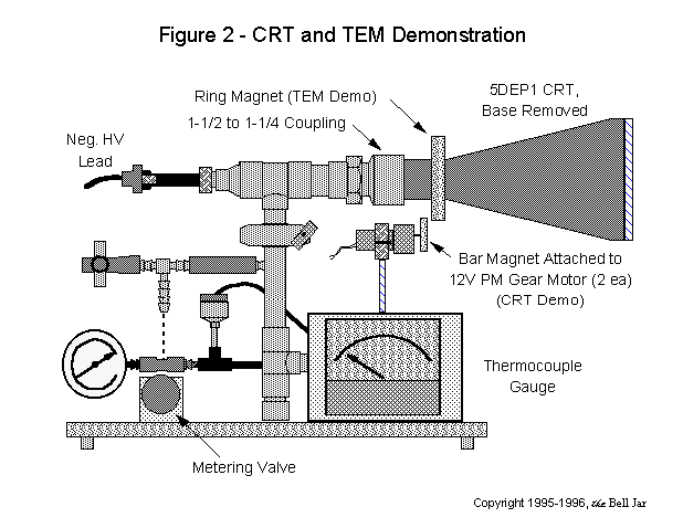
Figure 2 shows the system with an electron beam apparatus that may be constructed with more plumbing supply parts, a surplus cathode ray tube envelope, and some easy-to-obtain specialty parts.
The manifold and the electron gun are shown in Figure 3. This device with some experiments has been detailed in the Bell Jar. (See Volume 3, Number 2 and Volume 4, Number 4.)
Home tBJ Articles & Publications Chambers & Supplies Contact tBJ ©2008 Stephen P Hansen, the Bell Jar


